Application
The HHB02 scale has been approved for use in Austria for monitoring traffic and inspecting motor vehicles.

Types of motor vehicles
The HHB02 scale is approved for the following types of motor vehicles:
- It is only permissible to weigh two-tracked motor vehicles
- Minimum load per axle according to the minimum load of individual scale modules: 500 kg
- Number of axles: Due to the functionality of the HHB02 scale, there is, in principle, no limitation on the number of axles . A limitation arises, however, from the maximum length of the vehicle and the minimum spacing between two adjacent axles.
- Minimum axle spacing: 0.9 m
- Maximum overall length: Due to the design and function of the HHB02 scale, there is no limitation in the theoretical maximum overall length.
- Maximum track width: The maximum track width is 2.60 m. Lateral guides ensure that the entire width of the vehicle is on the dynamic road truck scale while driving across.
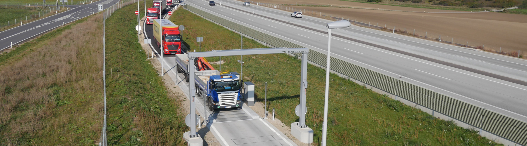
Weighing zones / approach and departure areas
The weighing zone consists of the inner and outer weighing zone with the approach and departure areas, as well as the dynamic road truck scale consisting of two weighing modules.
The approach and departures areas before and after the dynamic road truck scale each measure at least 18 m in total. The inner weighing zone consists of a continuous, reinforced-concrete foundation for at least 3 m before and at least 3 m after the dynamic road truck scale.
The foundation has cleaning and drainage channels and a frost-proof substructure in the area of the outer weighing zone.
The lateral lane limiters ensure that the entire width of the vehicle being measured is always driven across all of the weighing modules.
Signs installed in the approach area inform the driver of the speed range to be maintained.
In the outer weighing zone area, the vehicle is guided by clearly visible pavement markings at least 5 cm in width.
These standards are specific to Austria and can be adapted to meet national regulations in any country.
| Weighing plates 2 pieces | 12 km/h |
| Weighing plates 4 pieces | 30 km/h |
| Weighing plates 6 pieces | 30 km/h |
| Legal verification / approval | OE18/w010 |
| Accuracy class total weight | 2 (+/-1%) |
| Passage speed | 2 to 30 km/h |
| Minimum load total mass | 2.500 kg |
| Maximum load total mass | 50.000 kg |
| Scale interval for total mass | 50 kg |
| Accuracy class axle load | D (+/-2%) |
| Scale interval axle load dynamic | 50 kg |
| Scale interval axle load static | 20 kg |
| Accuracy class static | III |
| Maximum axle load | 20.000 kg |
| Minimum axle load | 500 kg |

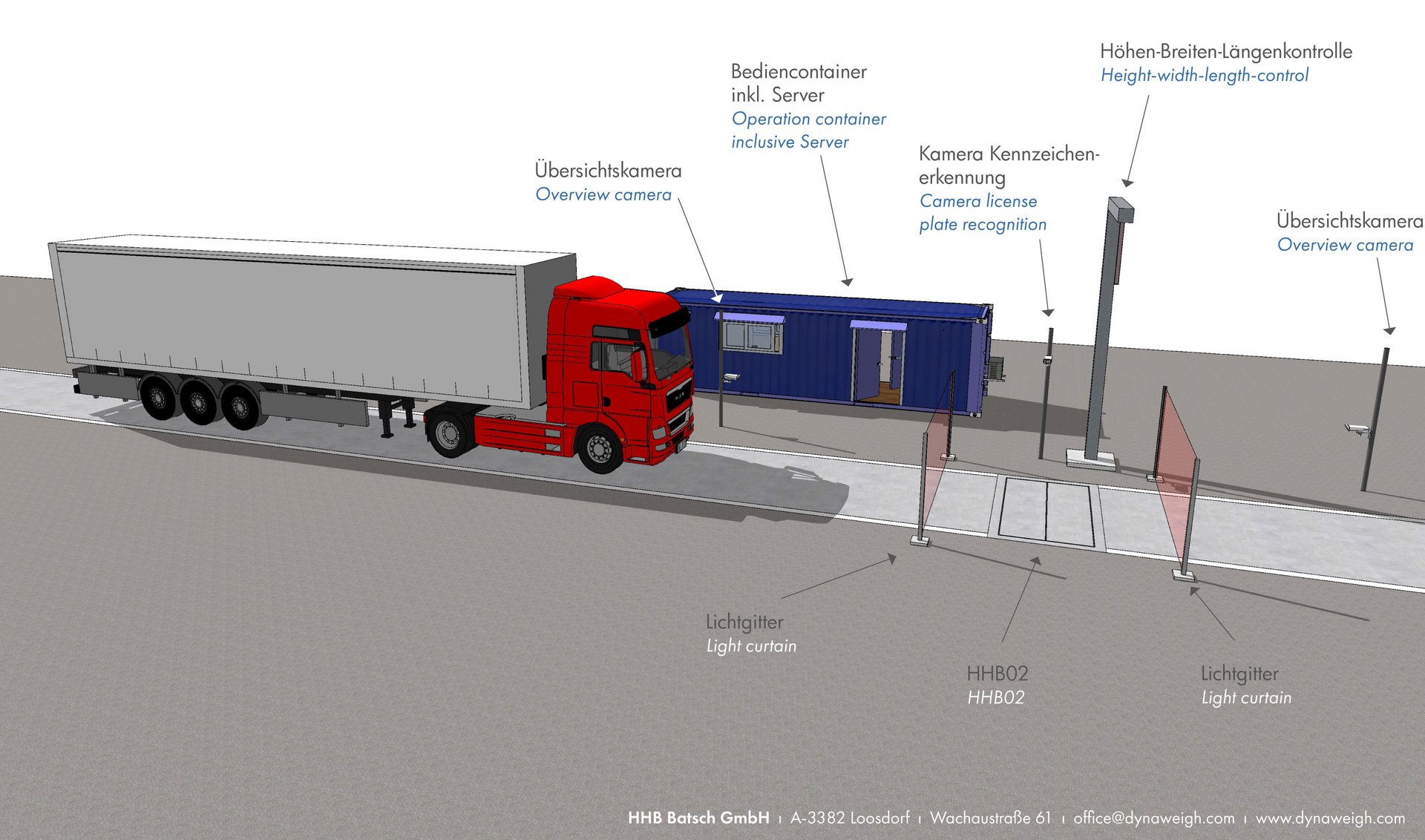
System description
This is an automatic, electromechanical dynamic road truck scale with electronic evaluation, model HHB02.
In detail, the HHB02 scale consists of a weighbridge with two weighing modules with load cells, approach and departure areas (consisting of inner and outer weighing zones), two evaluation units with a display and operator control device, a legally verifiable printer and/or data store.
One of the two evaluation devices additionally determines the total mass from the individual axle loads. The weights determined for the individual axles can be displayed.
For operator control from a second control station, an additional weighing terminal can be connected to the front-end device, mirroring the display and controls of the front-end device. This can also be used as a remote-control unit.
Axle loads determined in static operation are labeled accordingly. The actual scale is also designed as a monitoring scale for determining test loads (functional use as a non-automatic scale). In this case, only the master evaluation unit with one connected weighing module is used.


Weighing modules
The dynamic road truck scale consists of two weighing modules.
Each weighing module consists of a weighing plate and two load cells that correspond to a standard load transmission according to WELMEC 2.4/2001.
Each weighing module is connected to a dedicated evaluation unit (slave unit) that determines individual axle weights during passage. The total mass and legally verifiable axle weights are determined by a third evaluation unit (master unit) from the individual axle weights. In this variant, the two slave evaluation units consist of “black boxes,” without their own display and keyboard. The master evaluation unit in this variant consists of a terminal with a display and keyboard, but without a dedicated AD converter.
In a second variant, one of the two slave evaluation units also takes on the functions of the master unit.
In this case, the pure slave evaluation unit consists of a black box, and the combined slave/master unit consists of a full terminal with display and keyboard.
In both variants, an optional additional terminal with display and keyboard can be connected as a remote-control unit, mirroring the functions of the master unit for remotely controlling the scale.
Electronic and logical (software) structure
The HHB02 scale is electronically controlled by two or three evaluation units, depending on the variant.
From a logical standpoint, the HHB02 scale consists of two software components:
- Slave component
and - Master component
Exactly one slave component exists in one of the evaluation units. The job of the slave component is to capture weight data in raw format, filter and scale it, and determine individual axle loads.
Exactly one master component exists on the master evaluation unit, and can be installed alone or together with one of the two slave components. When passage is complete, the results of the two slave components are sent to the master component for further processing. Only the master components determines the calibratable total value of the total weight and the individual axle loads from the individual axles loads of the slave components.

Coordination of the weighing process, evaluation of the results from the master and slave evaluation units, and calculation and display of the total weight are performed by the master evaluation unit.
The evaluation units consist of:
- Display and
- Membrane keyboard
It is possible to connect a PC to the master evaluation unit to retrieve and process the weight values. The weight values are retrieved via a non-reactive interface without affecting the weighing process. The total weight and axle loads are determined and displayed exclusively in the master evaluation unit.
The master evaluation unit consists of a terminal and is equipped with two analog/digital converters for connecting DMS load cells. Another evaluation unit, with a display and keyboard, can optionally be connected to the master evaluation unit as a second display and remote-control unit. The display and controls are mirrored.
Software configuration
Two different drivers ensure correct functionality of the HHB02 scale: the HHB02 Master and the HHB02 Slave.
The functions of the HHB02 Master driver include:
- Calculating and displaying/outputting the total weight
- Calculating and displaying/outputting legally verifiable individual axle loads
- Checking permissible boundary conditions (speed, min/max loads, measurement duration)
- Communication with upper-level systems
- Process flow control with start/stop signals
The functions of the HHB02 Slave driver include:
- Determination of the partial axle loads
Weighing is carried out dynamically in fully automatic mode without operator intervention.
The vehicle drives across both weighing modules in the dynamic road truck scale, the individual axle weights are captured automatically, the total weight of the vehicle is calculated, and then the data is stored in the alibi memory, shown on the display, and provided for further processing.
Force transmission occurs directly into the strain-gage load cells (see detail view of weighing module support).
The strain-gage load cells are supplied with a clocked DC voltage from the evaluation units. The analog measurement signal provided by the strain-gage load cell is amplified, converted to digital values using the delta-sigma method, and processed into a final weighing value by the CPU.
The evaluation units (master and slave) determine the axle load weights independently of each other in their respective slave components. The legally verifiable axle load weights are determined, along with the total weight, in the master component on the master evaluation unit.
The following illustration shows the signal path of an HHB02 scale, consisting of the two weighing modules with load cells, via the associated master and slave components.

The HHB02 dynamic road truck scale consists of 2 weighing modules. One of the two weighing modules is connected to the slave evaluation unit, while the other is connected to the master unit. The following steps are used to determine the total weight:
- When the scale is in standby mode (that is, no weighing is currently taking place and the scale is waiting for a start signal), the slave components in the master and slave evaluation units continuously monitor the zero point to make sure it is within limits, and continuously set the connected weighing module to zero whenever the measurement signal has been within an Auto Zero Range for the period of the Minimum Zero Time.
- When a vehicle approaches the dynamic road truck scale, a start sensor triggers a signal that is registered by the master component in the master evaluation unit. The start signal can be triggered either by an external sensor (light curtain, induction loop, etc.) or manually by a user via the operator interface of the master evaluation unit.
- The vehicle moves its axles over the two weighing modules and generates a signal curve in each module for each axle.
- Both slave components record their current weight values at the Dynamic Update Rate of the ADM.
- When the vehicle is detected by the stop sensor at the end of the outer weighing zone, this is registered by the master component in the master evaluation unit. Alternatively, measurement can be stopped by the user at the operator interface of the master evaluation unit.
- Both slave components determine the speed and values for axle load weights for each captured axle from the saved signal curves. The slave components send their results to the master component on the master evaluation unit.
This data is processed in the master component on the master evaluation unit and the following values are determined:
A. Axle weight (legally verifiable)
B. Total weight (legally verifiable)
C. Average speed during passage (not legally verifiable)
As described in the weighing procedure, the slave components on each of the two evaluation units determine the axle loads from the signals captured by the load cells.
The axle loads thus determined are sent to the master component by the two slave components for further processing. The master component thereby determines the calibratable results for the total mass and the individual axle loads.
Directive-compliant data store
The directive-compliant data store secures legally verifiable weight values exclusively on a USB stick. There is no data of the directive-compliant data store in the internal memory of the master evaluation unit.
Entries in the directive-compliant data store are saved on the USB stick. A new file is created for each day. All of the files are saved in a folder named for the MAC address of the master evaluation unit.
For each measurement, one line is written in the active file for the current date. Write access to the USB stick is “blocking.” This means that all data must be fully written to the USB stick before the data is available for further processing and a new measurement can be started.
Accuracy classes
Total weight
The HHB02 scale is classified in the following accuracy class under /1/ (Amtsblatt für das Eichwesen Nr.3/2006 [Journal of Calibration )], Table 1 and /2/ (OIML R134), 2.1.1:
For determination of the total mass: 2
Axle load
The HHB02 scale is classified in the following accuracy class under /2/ (OIML R 134), 2.1.2:
For the determination of axle loads: D
Relationship between accuracy classes
The relationship between the accuracy classes for the determination of total mass and axle loads in Austria complies with Table 1 under /2/ (OIML R 134).
Error limits – capture while driving | Dynamic weighing
Total weight
The error limits for the determination of total mass while driving correspond to the (Amtsblatt für das Eichwesen [Journal for Calibration] No. 3/2006, latest version) and the directive /2/ (OIML R134).
Accuracy class 2
Calibration error limit as a percentage of vehicle mass ±1.0%
Axle loads
The error limits for the determination of axle loads while driving correspond to the (Amtsblatt für das Eichwesen [Journal for Calibration] No. 3/2006, latest version) and the directive /2/ (OIML R134).
Static weighing
The maximum permissible error for static weighing corresponds to the directive /2/, OIML R 134.
Scale increment, D
Division value, d
In accordance with /1/ (Amtsblatt für das Eichwesen [Journal of Calibration] Nr.3/2006, latest version), 6.1 and /2/ (OIML R134), 2.3, all of the devices in the HHB02 scale have the same division value d.
For the relationship between the accuracy class, the division value d, and the maximum vehicle mass, Table 15 applies (from /1/ (Amtsblatt für das Eichwesen [Journal of Calibration] No. 3/2006, latest version), 6.2 and /2/ (OIML R134).
Operating speed
The HHB02 scale works in a speed range from 2 km/h to 12 km/h.
Speeds that are outside this range will neither be displayed nor printed.
All speeds are rounded down mathematically to the next full 1 km/h for display and printing.
Internally, however, the HHB02 scale still works with the non-rounded values, for example when checking whether the maximum/minimum speed has been violated.