HHB01
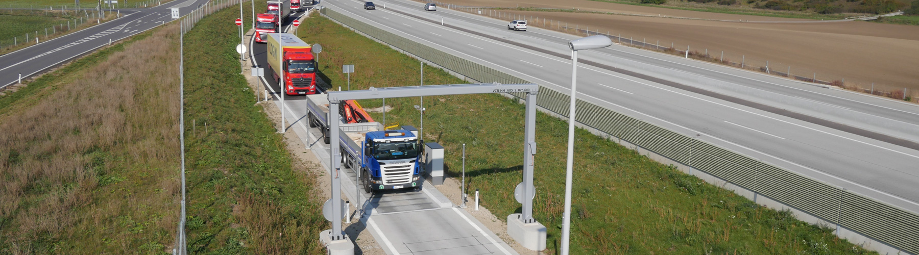
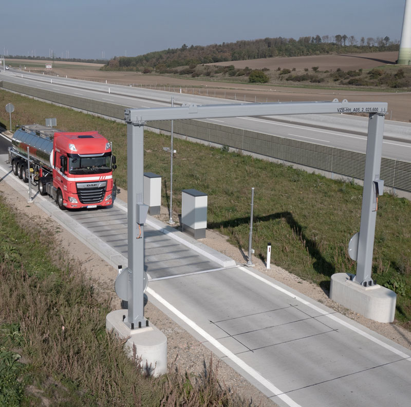
16-cell automatic dynamic road truck scale
This automatic weighing system fully complies with the requirements of EU Directive 2015/719:
COUNCIL DIRECTIVE 96/53/EC of 25 July 1996/ Amended by DIRECTIVE (EU) 2015_719 of 29 April 2015/ Proposal for amending by the European Commission of 17 May 2018 - for determining certain road vehicles circulating within the Community the maximum authorised dimensions in national and international traffic and the maximum authorised weights in international traffic.
In addition to the above EU directives, we can also cover NATIONAL legal requirements for various countries.

| Weighing plates | 16 pieces |
| Legal verification/approval | OE13/w601 |
| Accuracy class total weight | 2 (+/-1%) |
| Passage speed | 5 to 35 km/h |
| Minimum load total mass | 2.000 kg |
| Maximum load total mass | 50.000 kg |
| Scale interval for total mass | 50 kg |
| Accuracy class axle load | D (+/-2%) |
| Scale interval axle load dynamic | 50 kg |
| Maximum axle load | 20.000 kg |
| Minimum axle load | 500 kg |
The German National Metrology Institute (PTB - Physikalisch Technische Bundesanstalt) has issued a type test approval for Germany: no. DE-15-M-PTB-0007
Approval for legal verification GZ 4423/2013 Approval reference OE13/w600
Germany type test approval no.
DE-15-M-PTB-0007
Device for determining wheel and/or axle loads and/or total weight of driving road vehicles AT506047
European patent no. 2212660
Application
The HHB01 scale has been approved for use in Austria for monitoring traffic and inspecting motor vehicles.
Types of motor vehicles
The HHB01 scale is approved for the following types of motor vehicles:
- It is permissible to weigh two-tracked motor vehicles
- Minimum load per axle according to the minimum load of individual weighing modules: 500 kg
Due to the functionality of the HHB01 scale, there is, in principle, no limitation on the number of axles. A limitation arises, however, from the maximum length of the vehicle and the minimum spacing between two adjacent axles.
- Minimum axle spacing: 0.9 m
Due to the design and function of the HHB01 scale, the theoretical maximum overall length is determined by the length of the respective weighing zone.
Maximale Spur-Breite:
The maximum track width is 2.55 m. Lateral guides ensure that the entire width of the vehicle is on the dynamic road truck scale while it drives across.
System description
This is an automatic, electromechanical weighbridge with electronic evaluation, model HHB01.
In detail, the HHB01 scale consists of a weighbridge (with several weighing modules), approach and departure areas (consisting of inner and outer weighing zones), evaluation units with load cells, a display device, a calibratable printer and/or data store, and an operator control unit that determines the total mass and axle loads of road vehicles while they drive across the scale.
The evaluation unit consists of a network of several weighing terminals that determine partial results of the weights displayed in a coordinated and independent manner. A front-end device that mathematically combines the partial results is used to determine the total weight shown.
For operator control from a second control station, an additional weighing terminal can be connected to the front end, mirroring the display and controls of the front end. This can also be used as a remote-control unit.
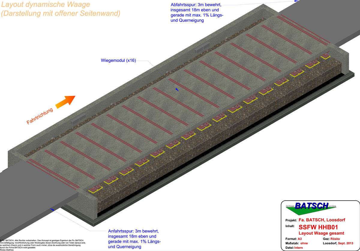
Weighing zones/approach and departure areas
The weighing zone consists of the inner and outer weighing zone with the approach and departure areas, as well as the dynamic road truck scale consisting of several weighing modules. The approach and departures areas upstream and downstream from the dynamic road truck scale each measure at least 18 m in total. The inner weighing zone consists of a continuous, reinforced-concrete foundation for at least 3 m upstream and at least 3 m downstream of the weighbridge. The foundation has cleaning and drainage channels and a frost-proof substructure in the area of the outer weighing zone. The lateral lane limiters ensure that the entire width of the vehicle being measured is always driven across all of the weighing modules. Signs installed in the approach area inform the driver of the speed range to be maintained. In the outer weighing zone area, the vehicle is guided by clearly visible pavement markings at least 5 cm in width.
These standards are specific to Austria and can be adapted to meet national regulations in any country.

Weighing modules
The dynamic road truck scale consists of 16 weighing modules.
Each weighing module consists of a weighing plate and two load cells on single-sided supports and equipped with a standard load transmission per WELMEC 2.4/2001.
Two of these weighing modules are combined to form a logical “weighing unit” that is recorded by a black box.
This means that the HHB01 scale consists of eight logical weighing units.
Evaluation unit/front end
Coordination of the weighing procedure, evaluation of the results of the individual black boxes, calculation and display of the total weight are all carried out in a front-end device.
The front-end device consists of:
• Display and • Membrane keypad
It is possible to connect a PC to the front-end device and use it to retrieve and process the weight values. The weight values are retrieved via a non-reactive interface without affecting the weighing process.
The total weight is determined exclusively in the front-end device.
The parameters for determining the weight are stored in the front-end device and used to evaluate the calculated results.
Black boxes
The black boxes consist of evaluation units, but without a display and control unit. The evaluation units are equipped with two ADM type analog/digital converters for connecting DMS scale substations.
Technical data for the ADM:
- Maximum of 8 DMS load cells at 350 Ω each
- Load cell impedance range 43 Ω to 4500 Ω
- Legally verifiable resolution of 6,000 d at max. 80% preload, internal resolution 524,000 d
- Least permissible input signal for applications with mandatory calibration 0.33 μV / d
- Measurement rate 50–400 readings per second
- Supply voltage for load cells: 5 V ± 5 % (clocked)"
The black boxes communicate with the front-end device via a network (TCP/IP). All black box settings are made via the front end and are securely saved there with a checksum. The storage location of the settings is the ADM in the front-end device, which can be secured against changes by means of a hardware jumper and seal.
When starting the application on the front-end device, these settings are sent to each black box via the network and used by it.
Each time the weighing results are transmitted from the black box to the front-end device, the checksum of the current settings is also sent to the front-end device.
Before processing the results, the front-end device checks the received and saved checksums and discards the weighing results if they do not match.
In this case, the user is informed of the error.
Force transmission and signal processing
The force is introduced directly into the strain gage load cell(s).
The strain gage load cell(s) are supplied with a clocked DC voltage from the black boxes. The analog measuring signal supplied by the strain gage load cell(s) is amplified, converted to digital values using the delta-sigma method, processed into a final weighing value by the CPU, and temporarily saved in the black box.
Upon request, the results are sent to the front-end device via a network connection.
The following illustration shows the signal path of a weighing unit, consisting of two weighing modules having two load cells each, via the corresponding black box to the front-end device.
The two outputs for load cell measurement signals in a weighing module are wired in parallel.
Alibi memory, reference data + checksum
The weight values are automatically compressed and stored with date and sequential number or with a non-resettable six-digit sequential number. The selection of the process is made during setup of the scale and can no longer be modified after calibration.
The data is backed up using a cryptologic hash function (SHA-256) for every individual entry in the alibi memory.
For every query, the checksum of the entry is calculated and compared with the saved checksum.
If the checksum for a query does not match, no weight value is displayed.

Directive-compliant data store
The directive-compliant data store secures calibratable weight values exclusively on a USB stick.
Retrieval and display of the directive-compliant data store
The directive-compliant data store can be retrieved and displayed at the front-end device
The HHB01 dynamic road truck scale consists of 16 weighing modules. Two of these weighing modules are combined into one weighing unit that is administered by a black box. All black boxes in the system are controlled from a central front-end device. The following steps are used to determine the total weight:
1) When the scale is in standby mode (e.g. no weighing is currently taking place and the scale is waiting for a start signal), the HHB01 scale continuously monitors the zero point for compliance with the limits. If the maximum load deviates by more than ±2 % from the calibrated zero point, the scale changes to an error state and displays a corresponding message.
2) When a vehicle approaches the dynamic road truck scale, a start sensor triggers a signal that is registered by the front-end device. The start signal is triggered either by an external sensor (light curtain, induction loop, etc.) or manually by the user via the front-end operator interface.
3) The front-end device controls the black boxes via the network, which then start the continuous recording of their current weight values.
When responding to the start command, the black boxes also send their current zero point to the front-end device, which checks it for compliance with the limits similar to 1).
4) The vehicle moves its axles over several weighing modules and generates a signal sequence on each module.
Each black box records its current weight values with the update rate of the ADM.
5) Steps 3) and 4) are performed for each axis and each weighing unit using two weighing modules
6) Once the vehicle is detected by the stop sensor at the end of the dynamic road truck scale, it is registered by the front-end device. Alternatively, the measurement can be stopped by the user via the operator interface.
7) The front-end device controls the black boxes, via the network, which then stop their recording of the weight values.
8) The front-end unit requests the results from the black boxes via the network.
9) The individual black boxes calculate the speed, values for the axle load weights as well as the distance to the preceding axle (starting with the second axle) from the stored signal sequence for each axle detected.
10) These values are compared in the front-end device. Values outside of the specification, such as excessive speeds, are detected and shown on the display.
The front end also determines the following values:
A) Total weight (legally verifiable)
B) Axle loads (legally verifiable)
C) Depending on the parameters of minimum/maximum axle group spacing, individual axles can be combined into axle groups.
This mean that axles with spacing within the configured range can be combined into a group.
D) Average speed during passage (not legally verifiable)
E) Acceleration/change in speed during passage (not legally verifiable)
Accuracy classes
Total weight
The HHB01 scale is classified as Accuracy Class 2 under /1/ (Amtsblatt für das Eichwesen No. 3/2006 [Journal of Calibration]), Table 1 and /2/ (OIML R134), 2.1.1 for determining the total mass.
Axle load
The HHB01 scale is classified as Accuracy Class D under /2/ (OIML R 134), 2.1.2 to determine axle loads.
Correlation between accuracy classes
The correlation between the accuracy classes for the determination of total mass and axle loads in Austria complies with Table 1 under /2/ (OIML R 134).
Error limits—Determination while driving | Dynamic weighing
Total weight
The error limits for the determination of total mass while driving correspond to the Journal for Calibration (and the Directive OIML R134).
Axle loads
The error limits for the determination of axle loads while driving correspond to the Journal for Calibration (and the directive OIML R134).
Static weighing
Not applicable. The HHB01 scale cannot be used to perform static weighing.
Scale increment, d
In accordance with /1/ (Amtsblatt für das Eichwesen [Journal of Calibration] No.3/2006), 6.1 and /2/ (OIML R134), 2.3, all of the devices in the HHB01 scale have the same scale increment d.
For the relationship between the accuracy class, the scale increment d, and the maximum vehicle mass, Table 15 applies (from /1/ (Amtsblatt für das Eichwesen [Journal of Calibration] No. 3/2006), 6.2 and /2/ (OIML R134).
Operating speed
The HHB01 scale works in a speed range of 5 km/h to 35 km/h.
Speeds that are outside this range will be neither displayed nor printed.
All speeds are rounded down mathematically to the next full 1 km/h for display and printing.
Internally, however, the HHB01 scale still works with the non-rounded values, for example when checking whether the maximum/minimum speed has been violated.